Excavator Wiring Harness Types Comparison: Functions, Applications, and Critical Precautions
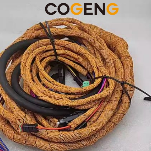
The electrical nervous system of your excavator—why harness quality determines machine reliability.
If hydraulic pumps are the heart of an excavator and hydraulic cylinders are the muscles, then the wiring harness is the nervous system. It carries power, sensor signals, and control commands to every corner of the machine—from the cab monitor to the engine ECU, from the joystick pilot controls to the proportional solenoid valves on the main pump.
A failed wiring harness can mimic almost any mechanical fault: sudden engine shutdown, unresponsive hydraulics, intermittent error codes, or complete electrical blackout. And because harnesses are routed through the most hostile environments on the machine—near hot engine components, through articulated joints, and exposed to moisture and debris—they demand robust design and proper maintenance.
This article provides a comprehensive comparison of wiring harness types found on modern excavators, their specific functions, and the critical precautions for installation and care. For replacement harnesses and electrical components compatible with Sumitomo, Hitachi, Kobelco, and other major brands, visit https://cogeng.net/.
Part 1: Wiring Harness Comparison by Type and Application
Excavator wiring harnesses are not a single assembly. They are typically divided into multiple sub-harnesses, each designed for a specific zone and function. The table below provides a direct comparison.
1.1 Main Harness Types Comparison Table
| Harness Type | Location & Routing | Primary Function | Connector Type | Wire Gauge Range | Environmental Exposure |
|---|---|---|---|---|---|
| Engine Harness | Engine block to ECU; high-temperature zone near exhaust and turbocharger | Carries injector signals, sensor data (crank position, cam position, boost pressure, temperature), alternator power, starter signal | High-temperature sealed connectors (Deutsch, Sumitomo TS/HD series); often with heat-resistant sheathing | 16–22 AWG signal wires; 8–12 AWG for alternator/starter | Extreme: heat, oil splash, vibration, chemical exposure |
| Cab Harness (Dashboard Harness) | Behind monitor panel, under operator seat, through console | Connects monitor display, switch panel, joystick potentiometers, safety lock solenoid, air conditioner, throttle dial | Multi-pin rectangular connectors; smaller sealed connectors | 18–24 AWG for signal and low-current circuits | Moderate: relatively protected but subject to dust, spilled liquids, and UV exposure at entry points |
| Main Frame Harness (Chassis Harness) | From cab rear wall along frame rails to pump compartment, valve bank, and rear of machine | The backbone: transmits control signals from cab to hydraulic valve solenoids, pressure sensors, angle sensors, lights, and horn | Heavy-duty circular connectors; large multi-pin bulkhead connectors at cab pass-through | 14–20 AWG for solenoid drive and sensor signal; 10–14 AWG for lighting and accessory power | Severe: water spray, mud, stone impact, vibration at frame mounting points |
| Boom/Arm Harness (Attachment Harness) | Along boom, arm, and bucket linkage | Powers and controls attachment auxiliary hydraulics (breaker, crusher, tiltrotator), work lights, camera, bucket angle sensor | Robust bayonet or threaded connectors; frequently disconnected for attachment changes | 14–18 AWG for solenoid and work light power | Extreme: direct weather, physical impact from debris, repeated flexing as boom/arm articulate |
| Battery/Power Cable Harness | Battery box to main disconnect switch, starter motor, alternator, and fuse/relay panel | High-current power distribution; unfused sections require meticulous insulation | Heavy-duty ring terminals, Anderson connectors, or bolted bus bar connections | 2/0–6 AWG for main power feeds | Moderate to high: corrosive battery fumes, potential for chafing against frame, moisture |
1.2 Detailed Type Analysis
Engine Harness
Design Characteristics:
Engine harnesses operate in the hottest part of the excavator. Wires routed near the exhaust manifold, turbocharger, or EGR cooler must use cross-linked polyethylene (XLPE) or silicone rubber insulation rated for continuous 150°C–200°C exposure. Standard PVC insulation will harden, crack, and short circuit within months in this environment. Protective sheathing is typically fibreglass or stainless steel braid rather than the split convoluted tubing used elsewhere.
Common Failure Points:
Chafing against engine brackets and sharp casting edges
Connector pin corrosion at the ECU from moisture wicking along wire strands
Insulation embrittlement near the turbocharger heat shield
Cab Harness
Design Characteristics:
The cab harness is the most connector-dense assembly on the machine. It interfaces with the monitor, switch panel, joystick potentiometers, safety lever limit switch, and HVAC system. Wires are typically lighter gauge because they carry low-current signals. The entire harness is often wrapped in non-adhesive PVC tape or flexible conduit for bundling and limited mechanical protection.
Common Failure Points:
Loose connector latches causing intermittent monitor or switch function
Worn insulation where the harness passes through the cab floor grommet
Corrosion on joystick potentiometer connectors from spilled coffee or rain entering through an open window
Main Frame Harness (Chassis Harness)
Design Characteristics:
This is the single most expensive and labour-intensive harness to replace. It connects the cab electrics to the pump compartment, main control valve, and rear chassis. Wires are thicker (14–16 AWG typically) because they drive proportional solenoids that can draw 1–2 amps continuously. The harness is protected by heavy-wall split convoluted tubing and secured with metal P-clamps every 300–400 mm. Bulkhead connectors at the cab wall allow cab removal without disconnecting every wire individually.
Common Failure Points:
Frame rail chafing: The number one cause of electrical faults. Improperly secured harnesses rub against frame edges until bare copper contacts the chassis.
Connector corrosion at the pump compartment: High-pressure washing forces water past connector seals; the resulting green corrosion causes high-resistance faults and solenoid malfunction.
Broken wires inside intact insulation: Vibration at clamping points fatigues copper strands internally, creating an open circuit that is invisible externally.
Boom/Arm Harness (Attachment Harness)
Design Characteristics:
The attachment harness must withstand continuous flexing as the boom raises and lowers and the arm crowds in and out. Wires use high-strand-count copper (Class K or higher, often 65/0.10 or finer stranding) to resist work hardening and breakage. Insulation is frequently thermoplastic elastomer (TPE) or polyurethane (PUR) for extreme flexibility and abrasion resistance. Connectors at the attachment end are often flat-face sealed connectors that can be repeatedly disconnected without seal damage.
Common Failure Points:
Flex fatigue at boom pivot points: Wires break internally where the harness bends repeatedly. A "Christmas tree" slack management loop is essential to distribute flex over a longer wire length.
Physical damage from falling debris: Rocks and demolition material can strike the harness directly on top of the boom.
Connector contamination during attachment changes: Disconnected auxiliary connectors lying in mud ingest moisture and dirt.
Battery/Power Cable Harness
Design Characteristics:
Power cables carry the full electrical load of the machine—up to 300 amps during starting. They use fine-strand copper welding-type cable for flexibility and are terminated with heavy-duty crimped ring terminals sealed with adhesive-lined heat shrink tubing. Correct crimping with a hex-die tool is non-negotiable; hammer crimps and poor soldering lead to high-resistance joints that melt under load.
Common Failure Points:
Loose battery terminal connections causing arcing, melted posts, and no-start conditions
Cable-to-frame chafing where the positive cable passes through a frame bulkhead without a grommet
Internal corrosion wicked into the cable from a poorly sealed terminal, appearing as green discolouration under the insulation several inches from the end
Part 2: Core Functions of Excavator Wiring Harnesses
Beyond simple power distribution, harnesses perform several critical functions that directly affect machine performance and diagnostics.
2.1 Power Distribution and Circuit Protection
The harness routes battery power through fusible links, fuses, relays, and the ignition switch to every electrical consumer on the machine. A properly designed harness includes:
Fusible links on main power feeds (smaller gauge wire that acts as a fuse at the battery terminal)
Diode-protected circuits to prevent back-feeding voltage spikes into the ECU
Dedicated ground wires for sensitive sensors, never relying solely on chassis ground
2.2 Sensor Signal Transmission
Sensors like the COGENG KM15-P02 pressure sensor output low-voltage (typically 0.5–4.5V) analog signals. The harness must preserve signal integrity through:
Shielded twisted-pair wiring for frequency-output sensors (speed sensors, crank position sensors)
Dedicated sensor ground reference that returns directly to the ECU, not to a local chassis ground point
Sufficient wire gauge to minimise voltage drop on long runs from the pump compartment to the cab ECU
2.3 Electromagnetic Compatibility (EMC)
Modern excavators with Tier 4/Stage V engines have multiple electronic control modules communicating via CAN bus. The harness layout must:
Route CAN bus twisted pairs away from high-current PWM solenoid wires to prevent induced noise
Maintain specified twist rates on communication wiring (typically 33–50 twists per metre)
Include 120-ohm terminating resistors at each end of the CAN bus, often built into the harness connectors
2.4 Safety Interlocks
The wiring harness implements mandatory safety functions:
Safety lock lever circuit: When the lever is raised, it opens a limit switch that de-energises the pilot solenoid lock valve, disabling all hydraulic functions. This is a hardwired safety circuit independent of software.
Engine shutdown circuits: Emergency stop buttons and low-oil-pressure shutdowns are wired to directly interrupt the fuel solenoid or ECU power, not reliant on software logic alone.
Part 3: Critical Precautions for Wiring Harness Handling and Installation
3.1 Before Removing a Harness: Documentation Is Everything
The single biggest mistake during harness replacement is failing to document the routing path and connector locations. Before removing a single cable tie:
Take clear photographs of every connector, clamp location, and branch point
Mark identical connectors with coloured tape or numbered labels—many solenoids use the same physical connector and swapping them can destroy an ECU output
Sketch the routing path noting which side of hoses and brackets the harness runs on
3.2 Harness Routing: The Root of Most Failures
When installing a new harness, routing is more important than the quality of the electrical connections:
Never route against sharp edges: Use rubber grommets at every bulkhead pass-through. Add spiral wrap or edge guard to any frame edge the harness crosses.
Maintain minimum bend radius: A general rule is 6 times the harness outer diameter for static routing, 10 times for flexing areas. Tighter bends stress the wire insulation and internal strands.
Secure with P-clamps at correct intervals: Every 300–400 mm for rigid frame sections, every 150–200 mm near vibrating components. A P-clamp that pinches the harness is as bad as no clamp at all—it should grip firmly without compressing the outer sheathing.
Allow slack at flex points: At boom and arm pivot joints, leave a loop (not a tight bend) that allows full articulation without pulling the harness taut.
Keep distance from heat sources: Route harnesses at least 150 mm from exhaust manifolds and turbochargers. If distance is impossible, install a heat shield and use high-temperature sleeving.
3.3 Connector Discipline: Waterproofing and Security
Inspect every connector seal: Before mating, check that the rubber wire seal and interface O-ring are present, clean, and undamaged. A missing seal will allow water ingress that travels inside the wire insulation for metres, causing failures far from the leak point.
Apply dielectric grease to seals: A thin film of silicone dielectric compound lubricates the seal during mating and adds a secondary moisture barrier. Do NOT pack grease into the terminal cavity itself—it can cause hydraulic lock during mating and unseat the terminals.
Listen for the click: Every sealed automotive-type connector has a positive latch. An audible click confirms full engagement. Visually verify the latch is fully seated.
Protect disconnected connectors: If a harness will be left disconnected for any period (e.g., when removing an attachment), install dummy plugs or cap the connector with a plastic bag and tape it mouth-down to prevent water accumulation.
3.4 Electrical Testing Before Power-Up
Before connecting the battery after any harness work:
Perform a continuity check on critical circuits: sensor 5V reference, sensor ground, CAN bus lines, and solenoid power feeds
Check for shorts to ground: Measure resistance between each power feed and chassis ground. Any reading below several kilo-ohms warrants investigation before applying power
Verify connector pin assignments against the machine's electrical schematic—never assume a replacement harness has the identical pinout to the old one, especially if the part number supersedes
3.5 Post-Installation Validation
Clear all fault codes before the first start after harness replacement
Run the engine and cycle all functions while observing the monitor for any recurring codes
Perform a wiggle test: With the engine running, gently flex the harness at each connector and clamping point while a helper watches for intermittent faults. This catches loose terminals and internal wire breaks that pass a static continuity test
Re-check after 50 hours: Inspect P-clamp tightness, connector latch engagement, and any signs of chafing after the machine has been working
Summary Comparison Table: Critical Precautions by Harness Type
| Harness Type | Top Installation Precaution | Top Maintenance Precaution |
|---|---|---|
| Engine Harness | Verify heat shield placement; use high-temp sheathing on all runs near turbo/exhaust | Inspect at every oil change for chafing and insulation hardening |
| Cab Harness | Ensure connectors are fully latched; pinched wires behind panels cause phantom faults | Keep cab interior dry; check joystick connector for corrosion |
| Main Frame Harness | Route away from frame edges; use protective edge guard at all contact points | Inspect after pressure washing for water in bulkhead connectors |
| Boom/Arm Harness | Provide adequate flex loop at pivot joints; secure against snagging on branches/debris | Check for external damage and internal wire breaks if function becomes intermittent |
| Battery/Power Harness | Use proper hex-crimp tools on all terminals; apply adhesive-lined heat shrink | Check terminal tightness and corrosion quarterly; replace immediately if insulation is discoloured from heat |
When to Replace Rather Than Repair
Field repairs using crimp butt connectors and electrical tape are a temporary measure. Consider a complete harness replacement when:
More than three wires in a bundle have damaged insulation
Green corrosion is visible on wire strands more than 50 mm from the connector end
Intermittent faults persist after cleaning all connectors and clearing codes (indicating internal wire breaks)
The harness outer sheathing has been worn through in multiple locations
For quality replacement wiring harnesses, connectors, sensors, and complete electrical component solutions for your excavator, browse the catalogue at https://cogeng.net/.
Related Keywords for Search:
excavator wiring harness types
engine harness vs cab harness comparison
excavator wire harness replacement
wiring harness installation precautions
excavator electrical harness maintenance
boom arm harness failure
excavator CAN bus wiring
hydraulic excavator wiring harness
COGENG excavator electrical parts
Disclaimer: All equipment brand names and model designations are used for compatibility reference only. COGENG is an independent supplier of aftermarket replacement parts and is not affiliated with any original equipment manufacturer mentioned. Always consult your machine's service manual and a qualified technician for specific electrical repair procedures. High-voltage and high-current circuits present shock and fire hazards if improperly serviced.


Comments
Post a Comment